
第六章 中断:概念、优先级与串口中断实验
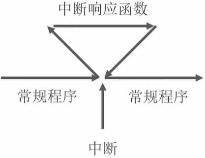
6.1 [中断]中断的概念
中断的基本概念
中断编程举例
闪灯程序
6.2 [中断]中断优先级
中断优先级的概念
用数字表示中断的紧急程度
中断优先级的表示方法
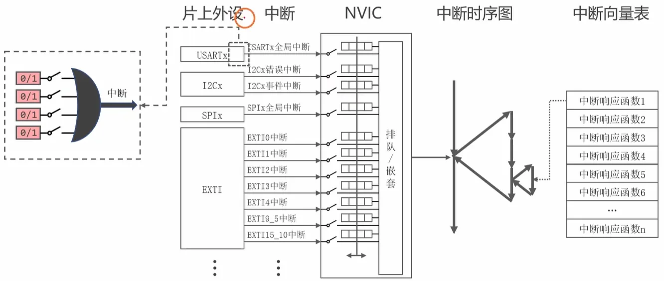
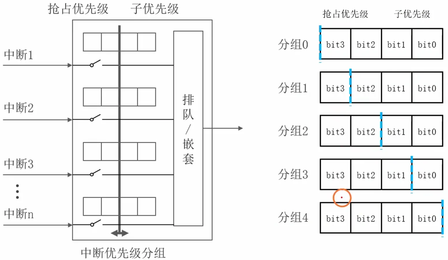
抢占优先级与中断嵌套
中断嵌套:更高优先级的中断打断正在执行的中断
子占优先级与中断排队
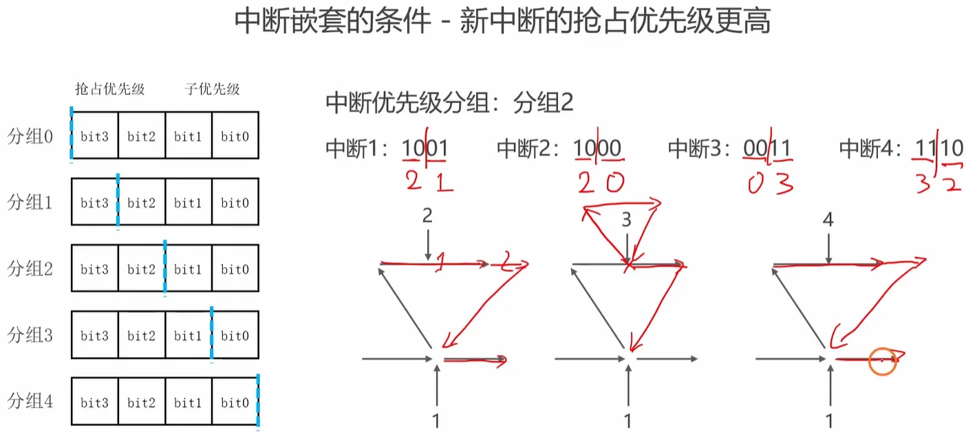
中段排队:优先级相仿时,等待前一个中断执行完,再处理新中断

练习题
6.3 [中断]串口中断编程实验
编写闪灯代码
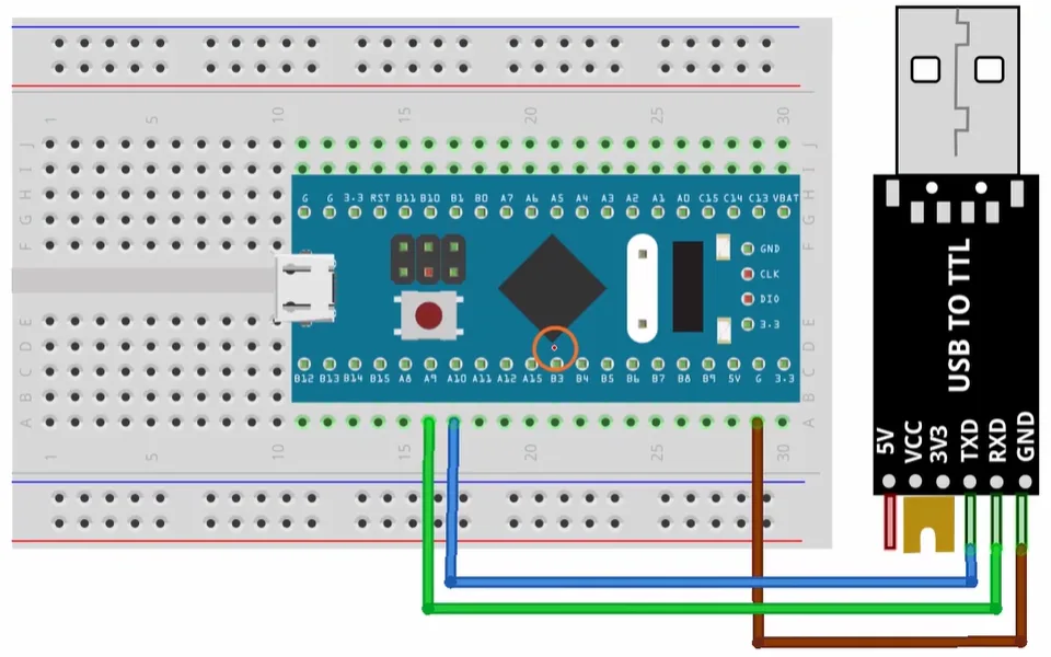
实验代码
#include "stm32f10x.h"
#include "delay.h"

uint32_t blinkInterval = 1000; // 闪灯间隔

void App_OnBoardLED_Init(void);

int main(void)
{
    App_OnBoardLED_Init();

    while(1)
    {
        GPIO_WriteBit(GPIOC, GPIO_Pin_13, Bit_RESET); // 亮
        Delay(blinkInterval); // 延迟
        GPIO_WriteBit(GPIOC, GPIO_Pin_13, Bit_SET); // 灭
        Delay(blinkInterval); // 延迟
    }
}

void App_OnBoardLED_Init(void)
{
    RCC_APB2PeriphClockCmd(RCC_APB2Periph_GPIOC, ENABLE);

    GPIO_InitTypeDef GPIO_InitStruct;
    GPIO_InitStruct.GPIO_Pin = GPIO_Pin_13;
    GPIO_InitStruct.GPIO_Mode = GPIO_Mode_Out_OD;
    GPIO_InitStruct.GPIO_Speed = GPIO_Speed_2MHz;

    GPIO_Init(GPIOC, &GPIO_InitStruct);
}
初始化串口
测试代码
#include "stm32f10x.h"
#include "delay.h"
#include "usart.h"

uint32_t blinkInterval = 1000; // 闪灯间隔

void App_OnBoardLED_Init(void);
void App_USART1_Init(void);

int main(void)
{
    App_OnBoardLED_Init();
    App_USART1_Init();

    My_USART_SendString(USART1, "Hello World. \r\n");

    while(1)
    {
        GPIO_WriteBit(GPIOC, GPIO_Pin_13, Bit_RESET); // 亮
        Delay(blinkInterval); // 延迟
        GPIO_WriteBit(GPIOC, GPIO_Pin_13, Bit_SET); // 灭
        Delay(blinkInterval); // 延迟
    }
}

void App_USART1_Init(void)
{
    // #1. 初始化IO引脚
    GPIO_InitTypeDef GPIO_InitStruct;

    // PA9 AF_PP
    RCC_APB2PeriphClockCmd(RCC_APB2Periph_GPIOA, ENABLE);

    GPIO_InitStruct.GPIO_Pin = GPIO_Pin_9;
    GPIO_InitStruct.GPIO_Mode = GPIO_Mode_AF_PP;
    GPIO_InitStruct.GPIO_Speed = GPIO_Speed_2MHz;
    GPIO_Init(GPIOA, &GPIO_InitStruct);

    // #2. 初始化USART1
    // 开启USART1的时钟
    RCC_APB2PeriphClockCmd(RCC_APB2Periph_USART1, ENABLE);

    // 初始化USART1
    USART_InitTypeDef USART_InitStruct;

    USART_InitStruct.USART_BaudRate = 115200;
    USART_InitStruct.USART_HardwareFlowControl = USART_HardwareFlowControl_None;
    USART_InitStruct.USART_Mode = USART_Mode_Tx | USART_Mode_Rx;
    USART_InitStruct.USART_Parity = USART_Parity_No;
    USART_InitStruct.USART_StopBits = USART_StopBits_1;
    USART_InitStruct.USART_WordLength = USART_WordLength_8b;

    USART_Init(USART1, &USART_InitStruct);

    // 闭合总开关
    USART_Cmd(USART1, ENABLE);
}

void App_OnBoardLED_Init(void)
{
    RCC_APB2PeriphClockCmd(RCC_APB2Periph_GPIOC, ENABLE);

    GPIO_InitTypeDef GPIO_InitStruct;
    GPIO_InitStruct.GPIO_Pin = GPIO_Pin_13;
    GPIO_InitStruct.GPIO_Mode = GPIO_Mode_Out_OD;
    GPIO_InitStruct.GPIO_Speed = GPIO_Speed_2MHz;

    GPIO_Init(GPIOC, &GPIO_InitStruct);
}
让 RxNE 标志位触发中断
USART_ITConfig
void USART_ITConfig(USART_TypeDef *USARTx,  // 串口名称,如USART1、USART2...
                    uint16_t USART_IT,      // 中断标志位名称
                    // 可选标志位:
                    // - USART_IT_TXE:发送寄存器为空
                    // - USART_IT_TC:发送完成
                    // - USART_IT_RXNE:接收寄存器非空
                    // - USART_IT_PE:奇偶校验错误
                    // - USART_IT_ERR:错误(帧错误/噪声错误/溢出错误)
                    FunctionalState NewState); // 中断开关:ENABLE(使能) / DISABLE(禁用)
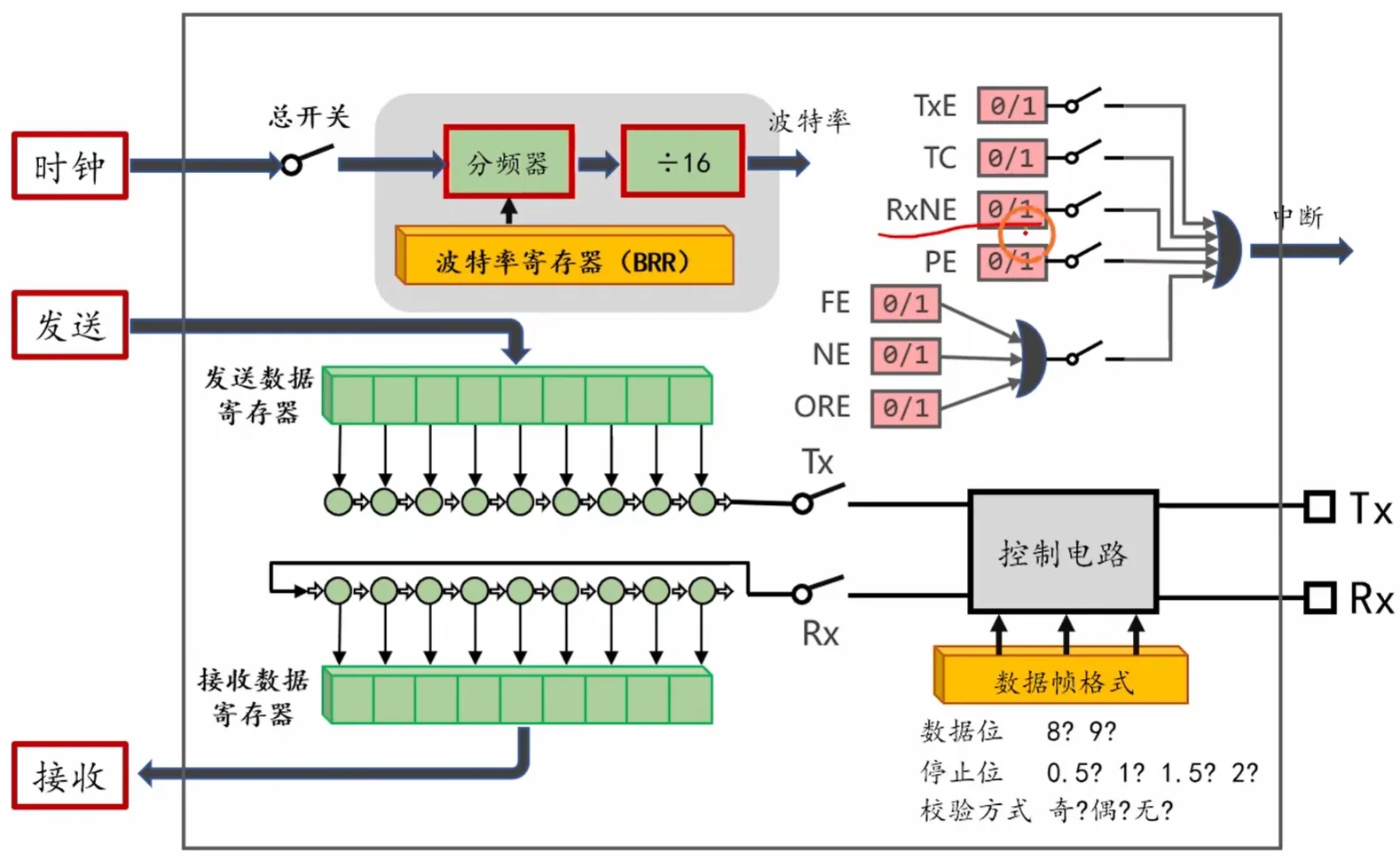
USART 硬件结构核心模块
- 时钟模块:总开关 → 分频器 →
÷16分频 → 波特率寄存器(BRR),用于生成目标波特率 - 发送模块:发送数据寄存器 → Tx 引脚,由控制电路管理发送时序
- 接收模块:Rx 引脚 → 接收数据寄存器,由控制电路管理接收时序
- 中断控制:多个中断标志位(
TxE/TC/RxNE/PE/FE/NE/ORE)经逻辑门后触发中断,可通过USART_ITConfig单独使能 / 禁用 - 数据帧格式:可配置数据位(8/9 位)、停止位(0.5/1/1.5/2 位)、校验方式(奇 / 偶 / 无校验)
配置 NVIC 模块
NVIC(嵌套向量中断控制器)模块是 Cortex-M3 的一部分。
1. 中断使能 / 失能(Interrupt Enable/Disable)
这是最基础的 “开关” 功能,用于控制某个中断是否具备被 CPU 响应的权限。即使外设(如 USART1)已配置好中断标志(如 RXNE),若 NVIC 未使能该中断,CPU 也不会处理这个中断请求。
- 核心函数:
NVIC_EnableIRQ()(开启中断)、NVIC_DisableIRQ()(关闭中断) - 实战示例(串口 1 中断):
NVIC_EnableIRQ(USART1_IRQn);
2. 中断优先级配置(Priority Configuration)
用于给不同中断分配优先级,解决多个中断同时触发时的响应顺序问题。STM32 的 NVIC 将优先级拆分为两类:
- 抢占优先级:高优先级中断可 “打断” 低优先级中断的执行(中断嵌套);
- 子优先级:同抢占优先级的中断,按子优先级高低排队响应(无嵌套)。
- 核心函数:
NVIC_Init()(通过结构体配置优先级) - 实战示例:给 USART1 中断配置抢占优先级 1、子优先级 0。
3. 中断嵌套管理(Interrupt Nesting)
基于优先级配置实现高优先级中断嵌套低优先级中断的能力。比如:串口 1 接收中断(高优先级)可打断正在执行的定时器闪灯中断(低优先级),待串口中断处理完成后,CPU 会回到定时器中断继续执行。这是 NVIC “嵌套” 特性的核心体现,保证紧急中断优先处理。
4. 中断挂起 / 解挂(Interrupt Pending/Unpending)
用于暂时搁置或恢复中断请求(即使中断已触发,也可控制是否立即响应)。挂起会让中断请求进入 “待处理队列”,解挂则触发 CPU 响应;也可主动清除挂起标志避免重复响应。
- 核心函数:
NVIC_SetPendingIRQ()(挂起中断)、NVIC_ClearPendingIRQ()(清除挂起) - 实战示例:
NVIC_ClearPendingIRQ(USART1_IRQn);(清除串口 1 中断挂起标志,防止重复响应)
NVIC_PriorityGroupConfig
void NVIC_PriorityGroupConfig(uint32_t NVIC_PriorityGroup);作用:配置 STM32 中断优先级分组,决定抢占优先级和子优先级的位数分配(共 4 位优先级位)。
| 分组 | 抢占优先级位数 | 子优先级位数 | 对应宏定义 |
|---|---|---|---|
| 分组 0 | 0 位 | 4 位 | NVIC_PriorityGroup_0 |
| 分组 1 | 1 位(bit3) | 3 位(bit2~bit0) | NVIC_PriorityGroup_1 |
| 分组 2 | 2 位(bit3~bit2) | 2 位(bit1~bit0) | NVIC_PriorityGroup_2 |
| 分组 3 | 3 位(bit3~bit1) | 1 位(bit0) | NVIC_PriorityGroup_3 |
| 分组 4 | 4 位(bit3~bit0) | 0 位 | NVIC_PriorityGroup_4 |
NVIC_Init
void NVIC_Init(NVIC_InitTypeDef *NVIC_InitStruct); // 初始化NVIC作用:根据传入的结构体参数,配置指定中断的通道、优先级(抢占 + 子优先级)和使能状态。
struct NVIC_InitTypeDef {
    // 中断的名称,对应stm32f10x.h中定义的IRQn类型(如USART1_IRQn)
    uint8_t NVIC_IRQChannel;

    // 抢占优先级:决定中断能否嵌套(高优先级可打断低优先级)
    uint8_t NVIC_IRQChannelPreemptionPriority;

    // 子优先级:同抢占优先级下,决定响应顺序(无嵌套能力)
    uint8_t NVIC_IRQChannelSubPriority;

    // 中断通道开关状态:ENABLE(使能)/ DISABLE(禁用)
    FunctionalState NVIC_IRQChannelCmd;
};
编写中断响应函数
完整实验代码
#include "stm32f10x.h"
#include "delay.h"

uint32_t blinkInterval = 1000; // 闪灯间隔

void App_OnBoardLED_Init(void);
void App_USART1_Init(void);

int main(void)
{
    NVIC_PriorityGroupConfig(NVIC_PriorityGroup_2);

    App_OnBoardLED_Init();
    App_USART1_Init();

    while(1)
    {
        GPIO_WriteBit(GPIOC, GPIO_Pin_13, Bit_RESET); // 亮
        Delay(blinkInterval); // 延迟
        GPIO_WriteBit(GPIOC, GPIO_Pin_13, Bit_SET); // 灭
        Delay(blinkInterval); // 延迟
    }
}

void USART1_IRQHandler(void)
{
    if(USART_GetFlagStatus(USART1, USART_FLAG_RXNE) == SET)
    {
        uint8_t dataRcvd = USART_ReceiveData(USART1);

        if(dataRcvd == '0')
        {
            blinkInterval = 1000;
        }
        else if(dataRcvd == '1')
        {
            blinkInterval = 200;
        }
        else if(dataRcvd == '2')
        {
            blinkInterval = 50;
        }
    }
}

void App_USART1_Init(void)
{
    // #1. 初始化IO引脚
    GPIO_InitTypeDef GPIO_InitStruct;

    // PA9 AF_PP
    RCC_APB2PeriphClockCmd(RCC_APB2Periph_GPIOA, ENABLE);

    GPIO_InitStruct.GPIO_Pin = GPIO_Pin_9;
    GPIO_InitStruct.GPIO_Mode = GPIO_Mode_AF_PP;
    GPIO_InitStruct.GPIO_Speed = GPIO_Speed_2MHz;
    GPIO_Init(GPIOA, &GPIO_InitStruct);

    // #2. 初始化USART1
    // 开启USART1的时钟
    RCC_APB2PeriphClockCmd(RCC_APB2Periph_USART1, ENABLE);

    // 初始化USART1
    USART_InitTypeDef USART_InitStruct;

    USART_InitStruct.USART_BaudRate = 115200;
    USART_InitStruct.USART_HardwareFlowControl = USART_HardwareFlowControl_None;
    USART_InitStruct.USART_Mode = USART_Mode_Tx | USART_Mode_Rx;
    USART_InitStruct.USART_Parity = USART_Parity_No;
    USART_InitStruct.USART_StopBits = USART_StopBits_1;
    USART_InitStruct.USART_WordLength = USART_WordLength_8b;

    USART_Init(USART1, &USART_InitStruct);

    // 闭合总开关
    USART_Cmd(USART1, ENABLE);

    // #3. 配置中断
    USART_ITConfig(USART1, USART_IT_RXNE, ENABLE);

    // #4. 配置NVIC
    NVIC_InitTypeDef NVIC_InitStruct;

    NVIC_InitStruct.NVIC_IRQChannel = USART1_IRQn;
    NVIC_InitStruct.NVIC_IRQChannelPreemptionPriority = 0;
    NVIC_InitStruct.NVIC_IRQChannelSubPriority = 0;
    NVIC_InitStruct.NVIC_IRQChannelCmd = ENABLE;

    NVIC_Init(&NVIC_InitStruct);
}

void App_OnBoardLED_Init(void)
{
    RCC_APB2PeriphClockCmd(RCC_APB2Periph_GPIOC, ENABLE);

    GPIO_InitTypeDef GPIO_InitStruct;
    GPIO_InitStruct.GPIO_Pin = GPIO_Pin_13;
    GPIO_InitStruct.GPIO_Mode = GPIO_Mode_Out_OD;
    GPIO_InitStruct.GPIO_Speed = GPIO_Speed_2MHz;

    GPIO_Init(GPIOC, &GPIO_InitStruct);
}
本文由 FormerlyXZ 创作, 采用CC BY-NC-SA 4.0 许可协议。
转载请注明出处,禁止商业使用。
评论
评论由 Giscus提供。首次评论需要在评论框里登录一次 GitHub(与页头的站点登录互相独立,这是浏览器安全限制), 之后当前浏览器会记住,不用反复登录;评论框里可以直接粘贴图片、拖入 PDF 等附件(GitHub 会帮你存好)。